3 Phase Converter Wiring Diagrams
- Static Phase Converter Wiring Diagram
- 3 Phase Converter Wiring Diagram
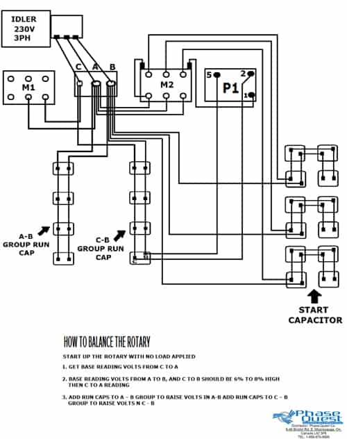
- 3 Phase Rotary Converter Wiring Diagram
Three Phase Motor Power & Control Wiring Diagrams 3-Phase Motor Power & Control Wiring Diagrams Three Phase Motor Connection Schematic, Power and Control.
Static Phase Converter Wiring Diagram
I figured that with a good write up to explain how it works to back it up it could prove useful for anyone who wanted to run three phase motors or build a balanced phase rotary converter for running three phase powered equipment off of a single phase source. It’s also known around my parts as a Miller system.
This is not the crappy low power, low efficiency, weak starting phase converters that you buy from the dealers. This is a well proven good high powered high efficiency design that can make most unmodified three phase motors run on single phase with both full starting torque and normal running power and efficiency.
I have built dozens of them and many are in daily usage applications and have given years of uninterrupted service working as both motors, phase converter power sources, and a few are now in dual use applications where they do double duty as a motor driving a mechanical load and as a balanced phase source rotary converter that runs additional loads.
by George Carlson
This page contains links to several circuits for building phase converters and magnetic starters.
Pavarotti and friends 1992 rapidshare. The converters are very simple but function well. They are designed to be easily constructed from readily available parts.
Use the static converter if you only plan to use a single 3-Phase motor, or where you wish to keep the machine portable. A good example of this would be a table saw that you wish to bring to a job site. Do not use the static type for multiple motors or for multiple speed motors. Motors run from a static converter will not deliver full name-plate power, but this is not generally a problem in the home shop. One thing that may appear to be different about these converters is that the Potential Relay uses AC Neutral as a reference. In many phase converters the Potential Relay is referenced to either L1 or L2. I have found using Neutral to be a far more effective way to operate the Potential Relay. Connected in this manner the relay will operate as it should, without intermittent opening and chatter.


3 Phase Converter Wiring Diagram
Use the rotary converter to supply the entire shop with three phase power. The rotary type converter will run any size motor from the smallest HP up to the HP rating of the idle motor used. Even resistive 3-Phase loads such as welders can be run from rotary converters.
The magnetic starters are used to run phase converters or individual motors. The main reason for using a magnetic starter is to protect the motor, phase converter, and operator from momentary power outages. The Deluxe version starter allows for remote control of a rotary converter and automatic shutdown when the shop lights are turned off. This helps prevent leaving the rotary converter on all night by accident. None of the starter circuits contain overload protection. Overload protection should be provided for each motor on a circuit including the Idle Motor used in the rotary converter. Quite often machine tools will have overload protection already installed.
The information in this article is from a presentation I did for the Houston Home Metal Shop Club. Please note that EPO and Ace Electronics are local surplus electronics suppliers in Houston, hopefully you will have such a supplier on your area.
3 Phase Rotary Converter Wiring Diagram
